4 Bit Ripple Counter Using D Flip Flop
The T flip flop is formed using the D flip flop. In D flip flop the output after.
Digital Design Counter And Divider
For time being ignore the input and output of T-Flip Flop.
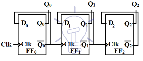
. Web One easy alternative method would be to use two TTL 7493s as 4-bit ripple counterdividers. Similarly with each negative transition of the output Q 0 the output Q 1 toggles and the same thing happens for Q 2 alsoHence the count sequences goes on. Web JK Flip-Flop D Flip-Flop T Flip-Flop D Latch Counters 4-bit counter Ripple Counter Straight Ring Counter Johnson Counter Mod-N Counter Gray Counter Misc n-bit Shift Register Priority Encoder 4x1 multiplexer Full adder Single Port RAM.
555 Sawtooth Oscillator. Of course standard IC asynchronous. 555 Square Wave Generator.
Full Verilog code for the multiplier is presented. Verilog code for Alarm Clock on FPGA 17. Web Edge-Triggered D Flip-Flop.
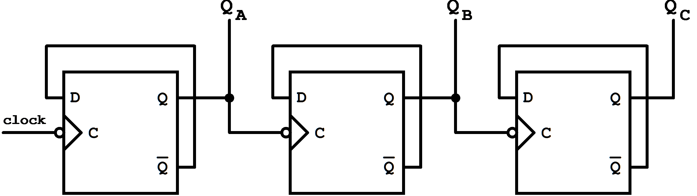
For 3 bit counter we. With each negative edge of the clock Q 0 toggles its state. Web 3 bit Synchronous Down Counter.
Verilog code for 16-bit RISC Processor 22. The primary intent of data-types in the Verilog language is to represent data storage elements like bits in a flip-flop and. Web Operation and Timing Diagram.
Circuit which will divide the input clock frequency by 2 4 or 8 times in fact any value to the power-of-2 we want making a. In synchronous counter clock is provided to all the flip-flops simultaneously. Web These gates are connected to the Clock CLK signal.
The starting count sequence is Q 2 Q 1 Q 0 111. We have two inputs ie clock and reset and q is output. Web How to load a text file into FPGA using Verilog HDL 15.
The Johnson counter is similar to the Ring counter. Johnson Counter Decade Counter. Web Therefore we can see that the output from the D-type flip-flop is at half the frequency of the input in other words it counts in 2s.
The logic diagram of a BCD counter using JK flip-flops is shown below. The two ICs would be cascaded together to form a divide-by-128 frequency divider as shown. Verilog Data Types.
The steps involves in design are. Web This project is to implement a 4x4 multiplier using Verilog HDL. Consider a 3-bit counter with Q 0 Q 1 Q 2 as the output of Flip-flops FF 0 FF 1 FF 2 respectively.
Let us assume the initial condition as Q C Q B Q A 000. In the T flip-flop a pulse train of little triggers is passed as the toggle input which changes the flip flops output state. Web Introduction Shift register Counters Ripple counter Ring counter Johnson counter.
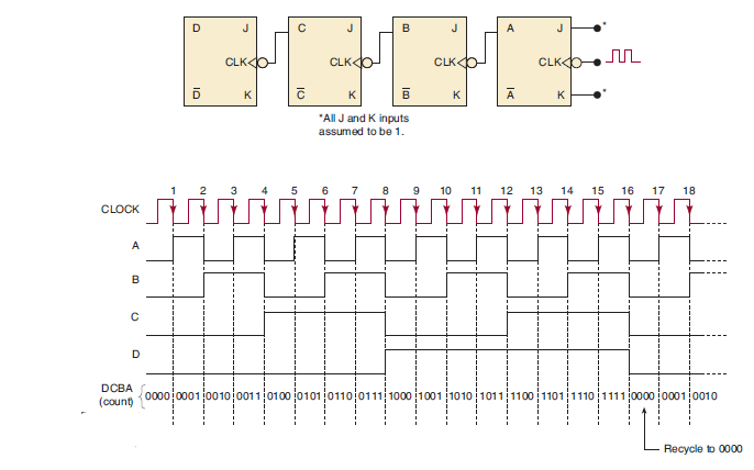
Verilog code for counter with testbench 21. Ripple Counters 10 41 BCD Ripple Counter Mod-10 A decimal counter follows a pattern of 10 states. The output q.
Since 128 16 x 8 one 7493 could be configured as a divide-by-16 counter and the other as a divide-by-8 counter. The top design block consists of four T-Flip Flop. Verilog code for Traffic Light Controller 16.
By cascading together more D-type or Toggle Flip-Flops we can produce a divide-by-2 divide-by-4 divide-by-8 etc. The technique being used is shiftadd algorithm but the different feature is using a two-phase self-clocking. Verilog Module Instantiations.
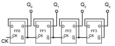
Web To proceed with Verilog Code we shall first understand the structure of the 4-bit Ripple Counter. A 4-bit binary ripple counter mod-16 is as follows. Circuit becomes complex as the number of states increases.
Next prev. Web Design steps of 4-bit synchronous counter count-up using J-K flip-flop. The circuit diagram of the T flip flop using SR flip flop is given below.
The only difference between the Johnson counter and the ring counter is that the outcome of the last flip flop is passed to the first flip flop as. Verilog code for D Flip Flop 19. As the input clock pulses are applied to all the Flip-flops in a synchronous counter some means must be used to control when an FF is to toggle and when it.
Decide the number of Flip flops N number of Flip flopFF required for N bit counter. Verilog code for comparator design 18. Verilog code for Full Adder 20.
Web In a ripple counter the flip-flop output transition serves as a source for triggering other flip-flops. Web Since the outputs are taken from the complements of the flip-flops. Let us consider the overall outside structure of Ripple Counter.
Web Ripple up-counter can be made using T-Flip flop and D-Flip flopDesigning of counters using flip-flops differs from each other with the type of flip-flop being used. Web D Flip-Flop T Flip-Flop D Latch Counters 4-bit counter Ripple Counter Straight Ring Counter Johnson Counter Mod-N Counter Gray Counter Misc n-bit Shift Register Priority Encoder 4x1 multiplexer Full adder Single Port RAM. Before going into the operation of the 3-bit synchronous counter learn how JK flip-flop and T flip-flop operates.
Asynchronous Counter

1 A 4 Bit Ripple Counter Circuit The Output Of One Flip Flop Clocks Download Scientific Diagram
Design Steps Of 4 Bit Asynchronous Up Counter Using J K Flip Flop
Digital Asynchronous Counter Ripple Counter Types Application


Comments
Post a Comment